Product
Datasheet

ACT48S / ACT48T
Target Applications
✈ Drone ◯ Mobile Robot 🦾 Robot Arm System
Key Features
  • 16-bit absolute magnetic encoder - 65,536 counts/rev (0.0055 deg/count)
  • High-speed and low-speed options are available
  • Current-based torque, speed, and position control modes
  • High-speed option: 5-16V DC, 3A rated, 48W max - stall torque 1.78 Nm, no-load speed 200 RPM (1200 deg/s)
  • Low-speed option: no-load speed is 4.9x slower at 40.82 RPM (244.90 deg/s), with the same 1.78 Nm stall torque
  • Multi-protocol: PWM (angle mode / continuous rotation) and Serial (half-duplex single-wire bus)
  • Serial bus: per-servo addressing with broadcast command support - see Section 2
  • Safety: overcurrent protection, thermal cutoff, ESD protection on all signal pins
  • Full metal gear train with ball-bearing output shaft; partial metal housing for passive heat dissipation; 25T standard spline
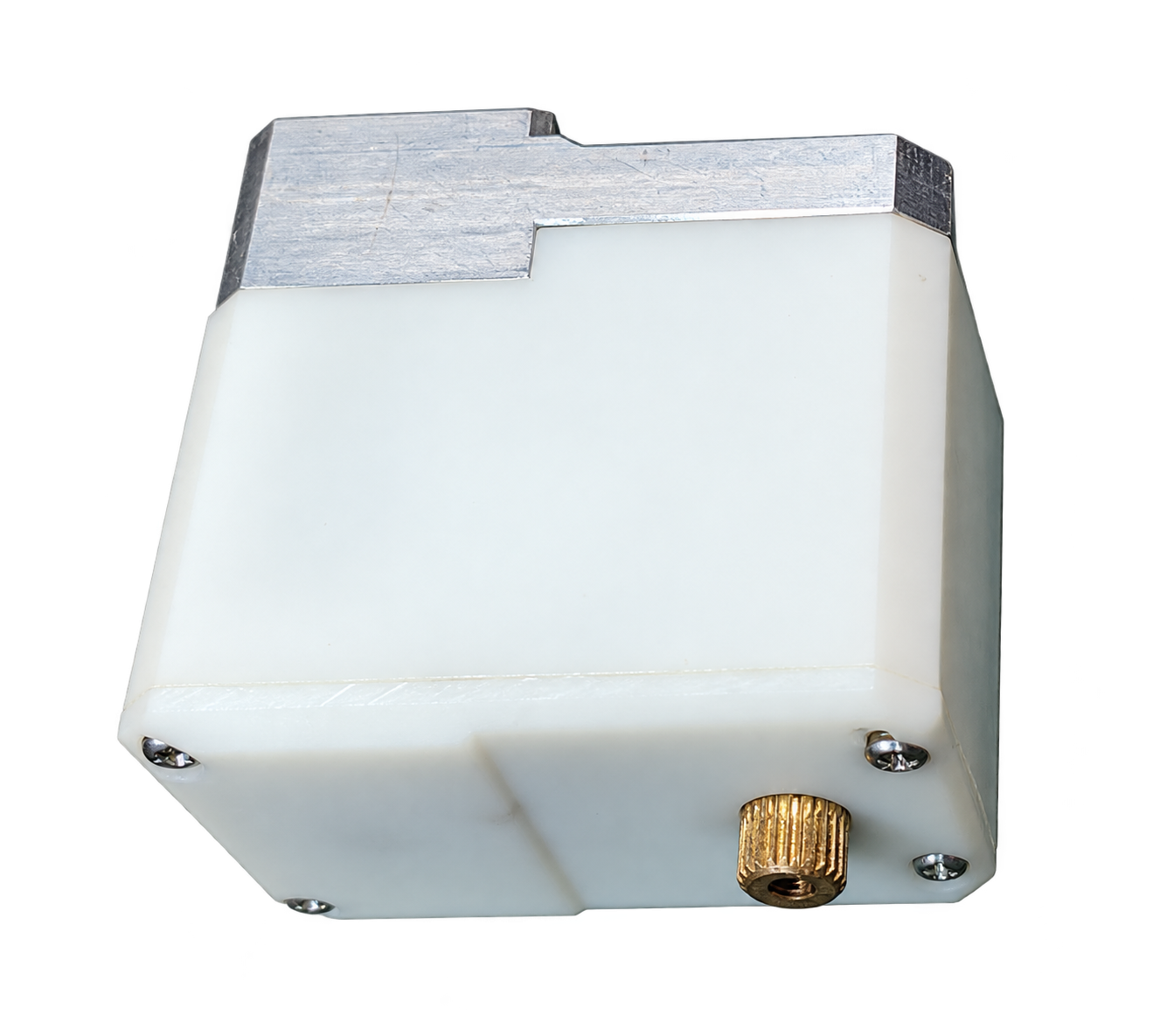
Product Image
ACT48S smart servo motor, background removed
Interface - Molex 5045 (3-pin)
Molex 5045 (3-pin)
1 GND Ground
2 VCC Power Input 5-16V, 3A max
3 SIG PWM / Serial (half-duplex)
Protocol: PWM / Serial (firmware-configured)
Connector: Molex 5045, 3-pin (2.54mm pitch)
Mating: Molex 22-01-1032, 3-pin female housing (2.54mm pitch)
Brief Specification
  • Supply Voltage5-16V DC
  • Max Current3A
  • No-Load Current16V / 400mA
  • Max Power48W
  • Stall Torque1.78 Nm
  • No-Load Speed200 RPM (1200 deg/s)
  • Encoder16-bit Magnetic (Absolute)
  • Input ProtocolPWM / Serial
  • Gear SystemFull Metal Gear
  • Output Shaft25T Spline, Ball Bearing
  • ConnectorMolex 5045, 3-pin
  • Operating Temp.-20 degC to +70 degC
  • Dimensions (W x D x H)26 x 46 x 45 mm
Dimensions
CAD Drawing

Specification

ACT48S / ACT48T
Full Technical Reference - ACT48 Product Datasheet Rev 1.0
Parameter Condition / Mode Value Unit
Mechanical
Dimensions (W x D x H)Housing, excl. mounting tabs26 x 46 x 45mm
Weight—TBDg
Gear System—Full metal gear train—
Output Shaft Bearing—Precision ball bearing—
Output Shaft Spline—25T standard spline - compatible with standard servo horns—
Mounting—M2 x 8 (4 front / 4 rear)—
Thermal Design—Partial metal housing - passive heat dissipation via case—
Power Supply
Supply VoltageOperating range5-16V DC
Max CurrentPeak input current3A
No-Load CurrentAt 16 V400mA
Max Power ConsumptionPeak48W
Overcurrent Protection—Yes - automatic shutdown on overcurrent—
Thermal Protection—Yes - automatic cutoff on overtemperature—
Performance
Stall TorqueACT48S1.78Nm
ACT48T1.78Nm
No-Load SpeedACT48S200 (1200 deg/s)RPM
ACT48T40.82 (244.90 deg/s)RPM
Control ModesPosition controlCurrent-based, closed-loop—
Speed controlCurrent-based, closed-loop—
Torque controlDirect current reference—
Encoder
Encoder Type—Magnetic (absolute)—
Encoder Resolution—16bit
Counts per Revolution—65,536counts/rev
Angular ResolutionPer count0.0055deg

Specification

ACT48S / ACT48T
Control Interface - Environmental Reference - ACT48 Product Datasheet Rev 1.0
Parameter Condition / Mode Value Unit
Control Interface
Input ProtocolPWMStandard RC servo PWM—
SerialHalf-duplex, single-wire UART—
Connector Type—Molex 5045, 3-pin (2.54mm pitch)—
Mating Connector—Molex 22-01-1032, 3-pin female housing (2.54mm pitch)—
ESD ProtectionSignal pinsYes—
Environmental & Reliability
Operating TemperatureContinuous-20 to +70degC
Storage TemperatureNon-condensing-20 to +85degC
Humidity (Operating)Non-condensing10 ~ 90% RH

Input Protocol Reference

ACT48S / ACT48T
PWM - Serial Interface - ACT48 Product Datasheet Rev 1.0
1. Input Protocol Overview

The ACT48 supports two input protocols on the SIGNAL pin. The active protocol is selected via firmware configuration. In PWM mode, the servo operates as a standalone actuator responding to position or speed commands. In Serial mode, multiple ACT48 units share a single signal line and respond to individually addressed or broadcast packets.

1-1. PWM

Standard RC servo PWM is decoded from a periodic pulse generated by the host controller. The meaning of the PWM pulse width is determined by control-table address 0x85 (Operating Mode). That mode cannot be changed from PWM input itself; it must be changed through the serial interface. PWM input supports 0x00 = Torque, 0x01 = Velocity, and 0x02 = Position. If 0x03 = Extended Position is selected, incoming PWM is ignored.

Parameter Value Note
Pulse Period20 ms (50 Hz)Standard RC servo period
Pulse Width RangeConfigurableSet by 0xB1 PWM Min and 0xB3 PWM Max; midpoint is their average
Resolution16-bit65,536 steps over full range
Operating Mode SourceRegister 0x85Selects Torque / Velocity / Position behavior for PWM input
Signal TimeoutConfigurableSet by 0xB5 PWM Timeout
Signal Level3.3V / 5V compatibleInput logic threshold TBD
PWM Mode Pulse Width - Action Description
Torque modePWM Min / midpoint / PWM Max - negative / zero / positive torque commandPWM pulse width maps to the torque command. 0xB1 PWM Min and 0xB3 PWM Max define the usable time range. Because torque units are power-based in this system, this is a power-control input mode.
Velocity modePWM Min / midpoint / PWM Max - negative / zero / positive velocity commandPWM pulse width maps to target velocity. 0xB1 PWM Min and 0xB3 PWM Max define the usable time range, and direction follows which side of the midpoint the pulse width lies on.
Position modePWM Min-PWM Max - minimum to maximum positionPWM pulse width maps linearly to target position over the configured position range, using the adjustable bounds set by 0xB1 PWM Min and 0xB3 PWM Max.
1-2. Serial Interface
The serial interface reference has been moved to a dedicated document. ACT48 uses Model Number 0x01.
See Actuator Serial Interface.
Gear Options

ACT48S / ACT48T
High-Speed And Low-Speed Mechanical Configuration - ACT48 Product Datasheet Rev 1.0
Overview

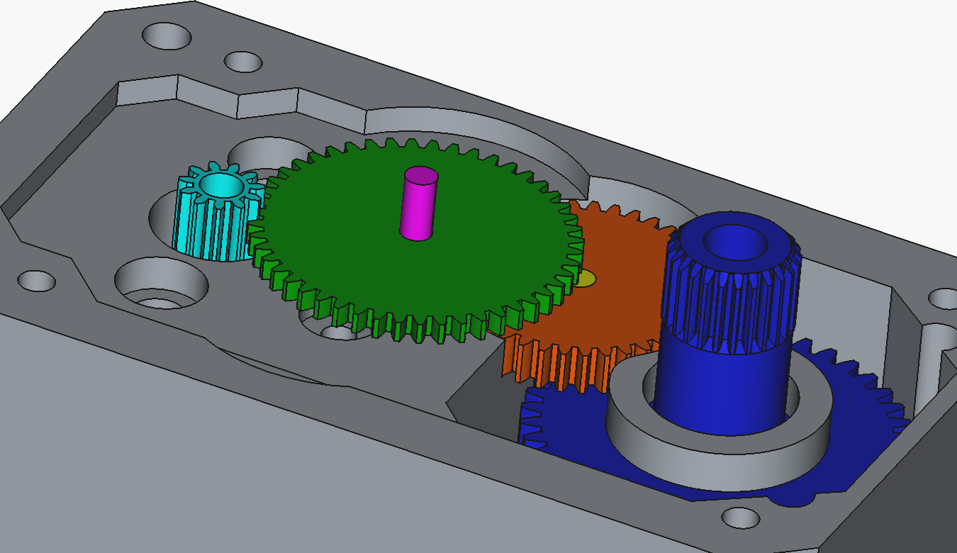
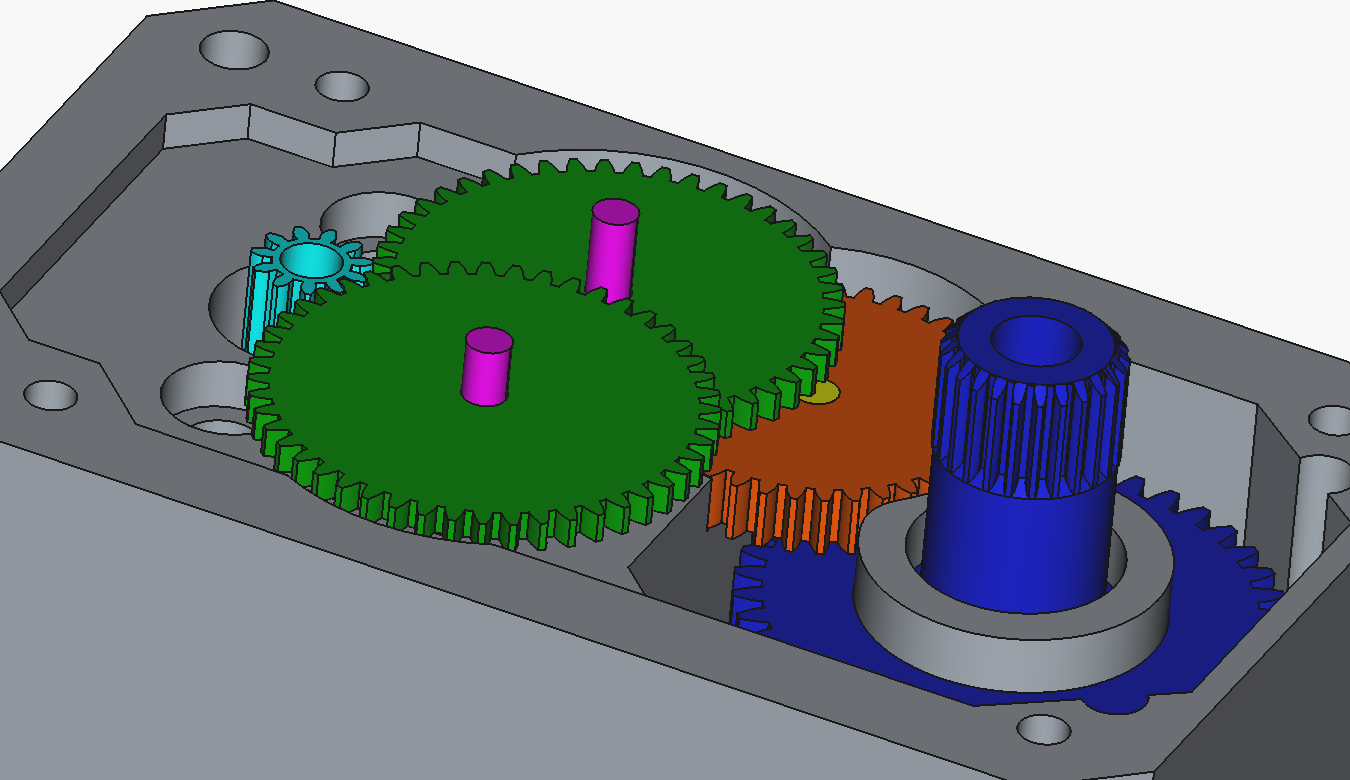
ACT48 is available in two gear-train configurations. ACT48S is the high-speed option and matches the 200 RPM (1200 deg/s), 1.78 Nm reference specification. ACT48T is the low-speed option. It reduces output speed by 4.9x through the internal gear arrangement while keeping the same 1.78 Nm stall torque.

In the low-speed configuration, the user can disassemble the servo and readjust the gear positions to convert the unit into the high-speed configuration. The electrical interface and protocol behavior stay the same; only the mechanical reduction path changes.

ACT48S Gear Placement
ACT48S gear layout
High-speed gear arrangement. This is the faster output configuration at 200 RPM (1200 deg/s) no-load speed.
ACT48T Gear Placement
ACT48T gear layout
Low-speed gear arrangement. Compared with ACT48S, this mode runs 4.9x slower at 40.82 RPM (244.90 deg/s) no-load speed while maintaining the same 1.78 Nm stall torque.
Mechanical Conversion Note
Variant No-Load Speed Stall Torque
ACT48S200 RPM (1200 deg/s)1.78 Nm
ACT48T40.82 RPM (244.90 deg/s)1.78 Nm

Pricing

ACT48S / ACT48T
Standard Unit Pricing - ACT48 Product Datasheet Rev 1.0
Part Number Naming Rule
ACT Actuator
48 Power
S Option
-
x Country
Prefix
ACTActuator
Power Code
48Maximum 48 W, single power option
Option
SHigh-speed option
TLow-speed option
Country of Origin
CChina
KKorea
XUnspecified
Sample Unit Pricing - ACT48T Series
Listed prices are for representative ACT48T sample units. Volume pricing available on request.
Part Number Description Qty Unit Price
ACT48T-X ACT48 low-speed servo motor, country code x 1 pcs US$ 80
ⓘ Volume pricing available for orders of 10 units or more - contact us for a quote. ✉ hyon646@gmail.com
◉ Corporate and laboratory volume orders qualify for significant discounts and dedicated technical support.
How to Order

Select your model using the Part Number Naming Rule above. Use ACT48S-X for the high-speed option and ACT48T-X for the low-speed option. Price on this page is listed for ACT48T-X.

Lead Time (stock) 1-3 business days
Lead Time (order) 4-6 weeks
Minimum Order Qty 1 pcs (standard) - 10 pcs (volume)
Payment PayPal - Bank Transfer - Other (on request)
Shipping Worldwide - DHL / FedEx / EMS
Contact hyon646@gmail.com
Document Revision History
Version Date Description
v1.0 2026-05-21 Initial Release