1. Output Format (Sensor → Host)
Each measurement is sent as a single ASCII line terminated by \n (0x0A).
The first character is the data type identifier.
| Prefix |
Example |
Unit |
Description |
| d |
d1234\n |
mm |
Distance measurement result (integer) |
| t |
t25.3\n |
°C |
Temperature measurement result (1 decimal) |
| v |
vlite\n * |
— |
Version string (response to v query) |
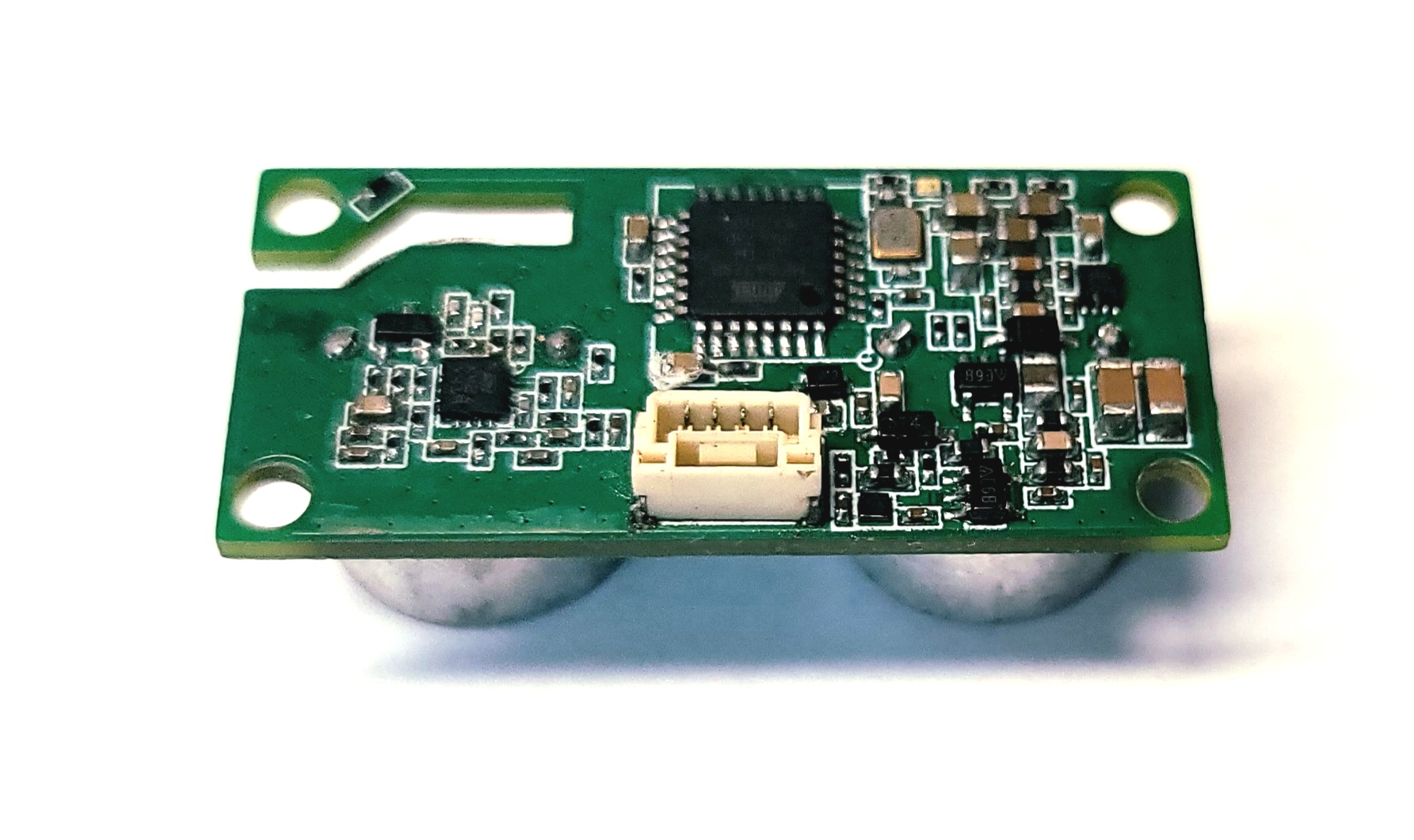
* Two version strings are possible: vlite = US0210 (2 transducers, TX + RX); vpro = US0310 (3 transducers, TX×2 + RX). The pro variant adds a second TX transducer, increasing echo reception probability at long range.
2. Command Reference (Host → Sensor)
Commands are ASCII strings terminated by \n.
The sensor echoes the accepted value back on the same channel (e.g., a100\n).
Settings are stored in non-volatile memory.
| Command |
Example |
Default |
Description |
| d |
d |
— |
Request the latest distance measurement immediately |
| t |
t |
— |
Request the latest temperature measurement immediately |
| v |
v |
— |
Query firmware version string |
| a* |
a100 |
100 ms |
Auto-output interval in ms. 0 = manual query only. Minimum 50 ms. |
| b* |
b115200 |
115200 |
Set baud rate. Allowed: 9600 / 19200 / 38400 / 57600 / 115200 / 230400 / 500000 / 1000000 |
| e* |
e100 |
100 |
Temperature measurement period (every N distance measurements) |
| p* |
p4 |
4 |
Max power level. Sets the upper limit of the automatic power selection (1–p*). e.g., p4=auto 1–4 (full range up to 10 m); p3=auto 1–3 (up to ~5 m); p0=sleep (transmitter off) |
| m* |
m1 |
1 |
Beam mode: 0=wide beam — 25 kHz low-frequency pulse, physically wide spread, longer range in open space · 1=balanced · 2=narrow beam — 60 kHz high-frequency pulse, tight beam, less interference, higher directional accuracy |
| y* |
y0 |
0 |
I/O options bitmask: bit0=checksum · bit1=binary output · bit2=beep output |
| r |
r |
— |
Factory reset — restores all defaults and plays a melody † |
* Sensor replies with the accepted value after any configuration command (e.g., a100\n → a100\n).
† Factory reset can also be triggered by shorting the RX and TX pins together before applying power.
3. Power Level Reference
p* sets the maximum power level. The sensor automatically selects the appropriate power level (1 through p*) based on the measured distance — it does not lock to a single level.
Setting a lower maximum reduces the effective range and limits interference.
| p* |
Level |
Max Range (this level) |
Note |
| 0 |
Sleep |
Transmitter off |
No measurement; ~20 mA standby |
| 1 |
Low Power |
Short range |
Lowest interference; reduced current |
| 2 |
Mid Power |
Mid range |
— |
| 3 |
High Power |
Up to ~5,000 mm |
Auto range: levels 1–3 |
| 4 |
Ultra-High Power |
Up to 10,000 mm |
Default. Auto range: levels 1–4. Flat surface required above 5 m. |